Guide to BMW CIP Programming with Maxisys Pro
1. BMW Programming Notes
– Connect an Autel or BMW approved battery charger to the vehicle, and ensure battery voltage is between 13V and 14V.
– Turn off all the electrical equipment, such as air conditioner, headlamps, turn signal lamps, wipers, etc. Unstable current will abort programming.
– Turn off wipers or cleaning system. Wipers may be active during programming, so please make sure there is enough space.
– Please check all the control units are installed and function properly before programming.
– Troubleshoot or clear DTCs of the vehicle before programming.
– Please set the correct date first. It will be recorded into the control units during programming and coding.
– Do not turn the ignition off during programming and coding unless specifically instructed to do so by MaxiSys Pro.
– Do not activate or move any part of the vehicle, such as windows, doors, the steering wheel, seats, buttons and other adjusting knobs. Failure to do so may abort programming.
Note: This document is built up based on BMW V3.00. It only applies to BMW V3.00 or later versions.
2. Entering CIP Main Interface
Tap ‘CIP (Coding, Individualisation, Programming)’.
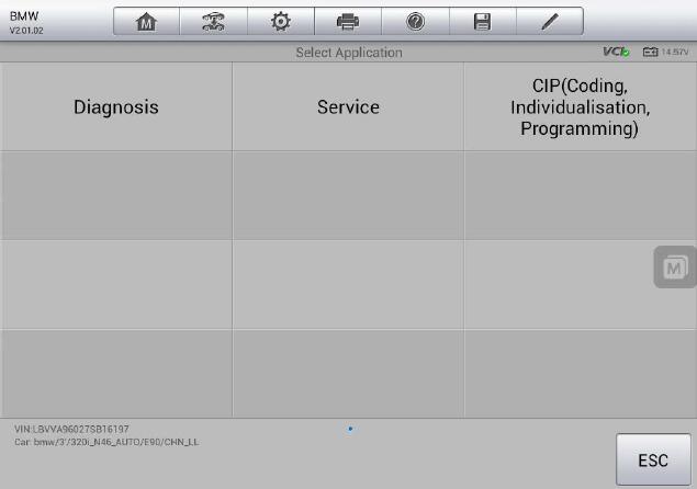
For vehicles performed CIP function with Autel Scanner MaxiSys Pro for the first time, please refer to 2.1 Initial Entering CIP.
For vehicles performed CIP function with MaxiSys Pro before, MaxiSys Pro will save the previous session automatically, and a prompt message will pop up to confirm whether to use the saved session. Please refer to 2.2 Re-entering CIP for additional information.
Note: MaxiSys Pro can only store up to 5 vehicle sessions. It will prompt you to remove some unnecessary ones if there are more than 5 sessions. Please refer to 2.2 Re-entering CIP.
2.1 Initial Entering CIP
MaxiSys Pro will read the current vehicle configuration information from CAS and LM/FRM when entering CIP for the first time, so CAS and LM/FRM cannot be replaced at the same time. Vehicle information will be shown as figure 2.2. You can
scroll through the list by sweeping your finger up and down to see more information.
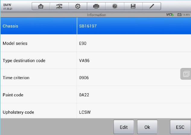
Tap ‘Edit’ to revise vehicle configuration information and the related interface will be shown as figure 3. You can scroll through the list by sweeping your finger up and down to see more information.
Note: To avoid the issue that the vehicle cannot work properly after revising the configuration information, it’s recommended to note down the current configuration information.
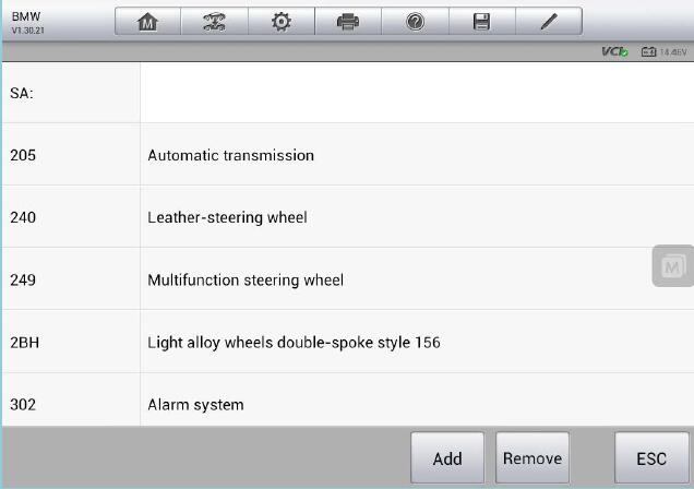
Tap ‘Add’ or ‘Remove’ to do the corresponding operation, and then tap ‘ESC’.
You will be prompted to confirm the revised configuration information, as shown in figure 4.
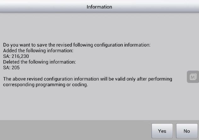
Tap ‘Yes’ to save the information, or tap ‘No’ to cancel the changes. The above revised configuration information will be valid only after performing corresponding programming or coding.
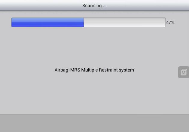
Then MaxiSys Pro will communicate with all control units. This step will take several minutes, which is based upon vehicle specifications, as shown in figure 5.
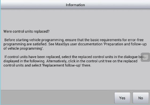
MaxiSys Pro will ask whether the control units have been replaced, as shown in figure 2.6. If the control units have been replaced, tap ‘Yes’ to select the replaced control units. Alternatively, tap ‘No’.
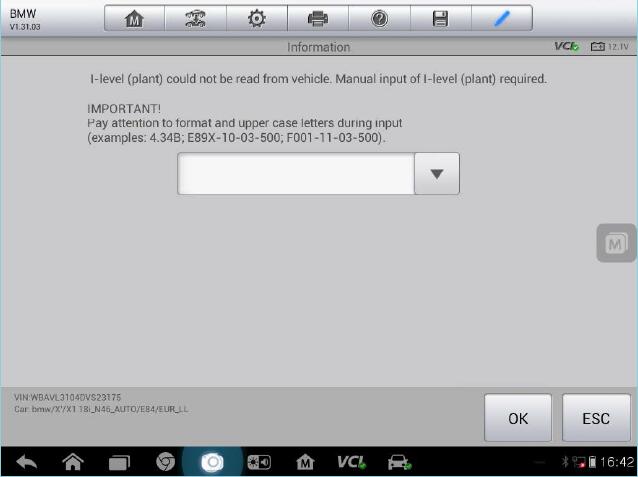
MaxiSys Pro will read integration level (I-level) from vehicle after performing all the above procedures. If the integration level could not be read from vehicle, manual input is required, as shown in figure 7.
If the vehicle integration level is very new, the following message in figure 8 may appear on the screen.
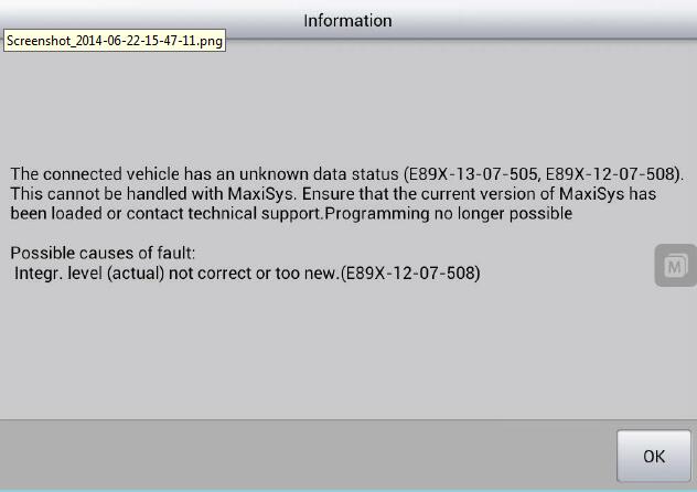
This shows that the vehicle integration level is newer than the one stored in MaxiSys Pro, and programming function is not recommended.
MaxiSys Pro will then read related information from each control unit to confirm whether it needs to be replaced or upgraded. After that CIP Main Interface will be shown. Please refer to 2.3 CIP Main Interface for detailed information.
2.2 Re-entering CIP
If CIP function has been performed before on the vehicle, MaxiSys Pro can save the previous session which records the configuration information. When MaxiSys Pro re-enters CIP, a prompt message will pop up to confirm whether to use the saved session, as shown in figure 9.
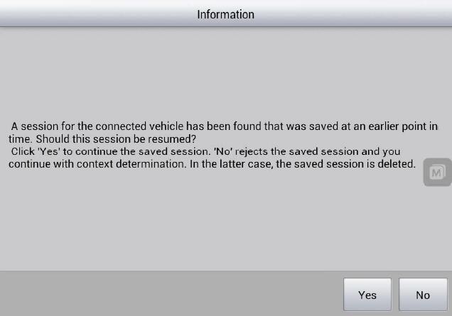
Tap ‘Yes’ to continue the saved session without establishing communication with vehicle again. This will realize fast access to CIP. Tap ‘No’ to reject the saved session, and MaxiSys Pro will establish communication with vehicle just as the procedure in initial entering CIP. Please refer to 2.1 Initial Entering CIP for additional information.
It is recommended not to use the session saved long time ago for the actual information of the vehicle may have changed.
MaxiSys Pro is set to only store up to 5 vehicle sessions. It will prompt you to remove some unnecessary ones if there are more than 5 sessions, as shown in figure 10
.
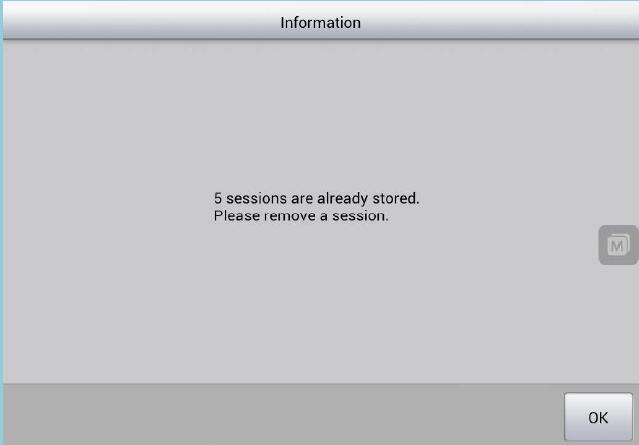
Tap ‘OK’ and a list of vehicle record will display. You can select the sessions to be removed, as shown in figure 11.
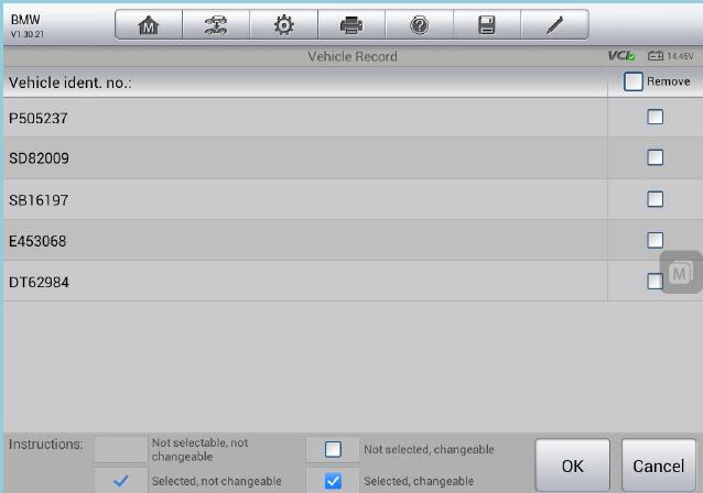
Select the sessions to be removed and tap ‘OK’. The message below will display on the screen, as shown in figure 12.
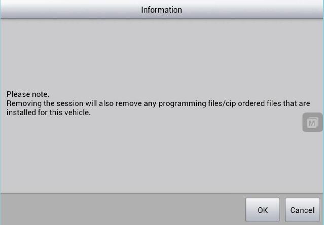
Tap ‘OK’ to remove the selected sessions. Then re-entering CIP is required.
2.3 CIP Main Interface
CIP Main Interface typically includes the following items, as shown in figure 13.
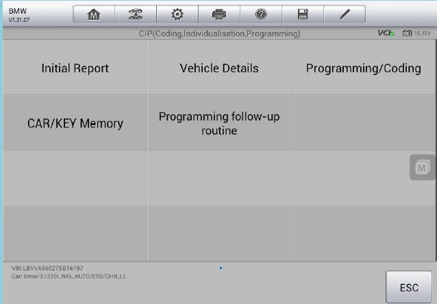
– Initial Report
Displays the information of control units to be replaced or upgraded and the estimated upgrade time.
– Vehicle Details
Displays vehicle configuration information.
– Programming/Coding
Performs programming and coding. Please refer to 3. Programming/Coding for additional information.
– CAR/KEY Memory
Performs personalized setting.
– Programming Follow-up Routine
Displays a list of special functions to be performed after programming and coding.
3. Programming/Coding
Programming/Coding interface typically includes the following items, as shown in figure 14.
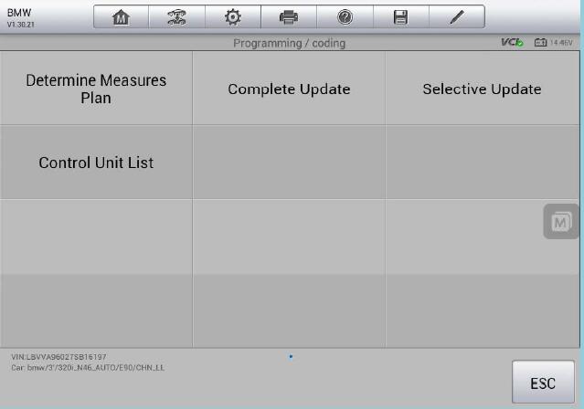
– Determine Measures Plan
Lists the upgrade plan automatically calculated by MaxiSys Pro.
Please refer to 3.1 Determine Measures Plan for additional information.
– Complete Update
All the ECUs available to programming/coding are checked by default.
Please refer to 3.2 Complete Update for additional information.
– Selective Update
Manually selects the ECUs you want to perform programming/coding.
Please refer to 3.3 Selective Update for additional information.
– Control Unit List
Displays all the control units, and you can perform diagnosis, programming,
coding, and special functions to the specific ECU. Please refer to 3.4 Control Unit List for additional information.
3.1 Determine Measures Plan
Determine Measures Plan shows a list of tasks for the current vehicle set by MaxiSys Pro, as shown in figure 15. You can scroll through the list by sweeping your finger up and down to see more information.
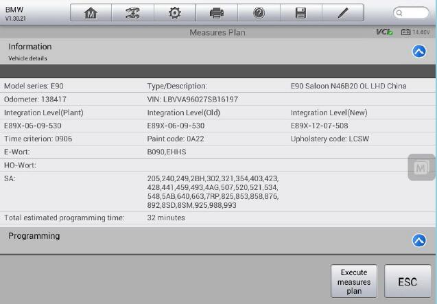
Tap ‘Execute measures plan’, and a prompt message of turning off engine and switching on ignition will pop up on the screen, as shown in figure 16.
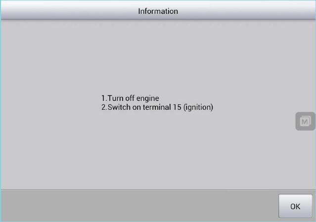
After confirming that engine is turned off and ignition is switched on, tap ‘OK’. If MaxiSys Pro needs to be connected to the Internet to download configuration file, the following message will display.
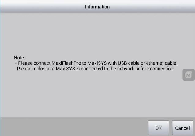
Disconnect MaxiSys Pro from vehicle (not a must), take Autel Maxisys Pro MS908P to the place with Internet connection, tap ‘OK’ after the network is connected, and then MaxiSys Pro can download configuration file from server, as shown in figure 18.
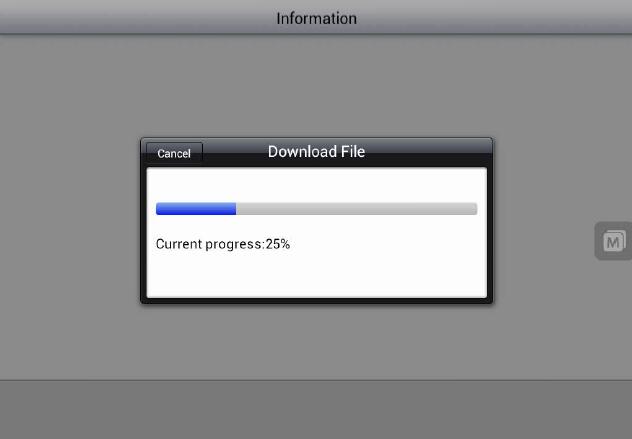
When download is complete, the following message will display.
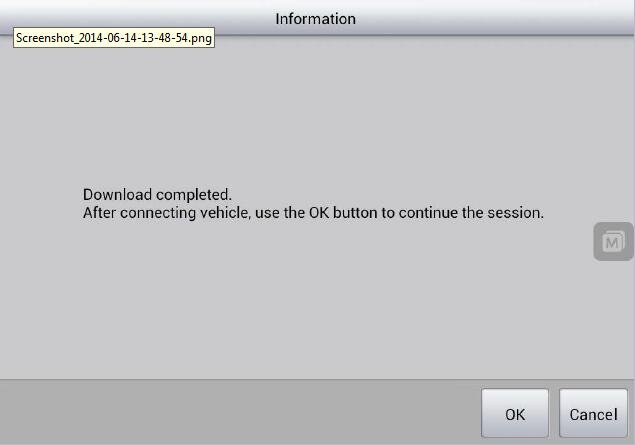
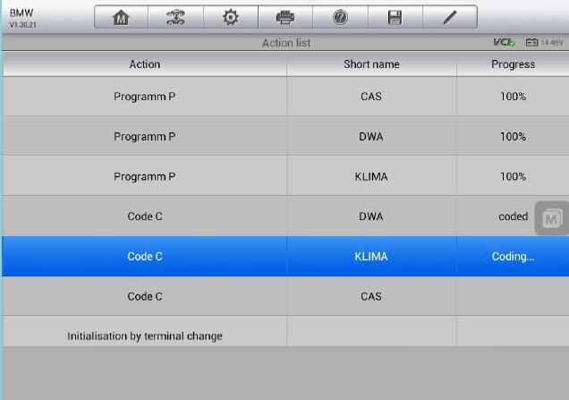
Please check MaxiSys Pro is connected with vehicle first, and then tap ‘OK’ to execute the plan. If there are programming tasks, the control units in programming will show the progress in percentage, as shown in figure 20 and figure 21.
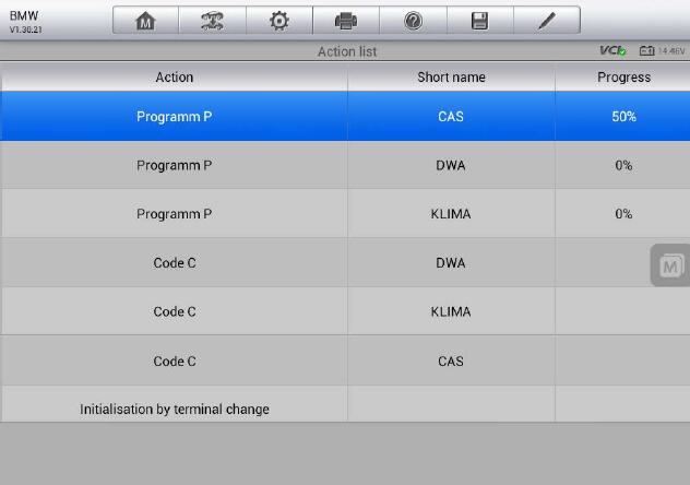
A prompt message of turning off ignition and removing the key from key slot will pop up when performing CAS programming, as shown in figure 22.
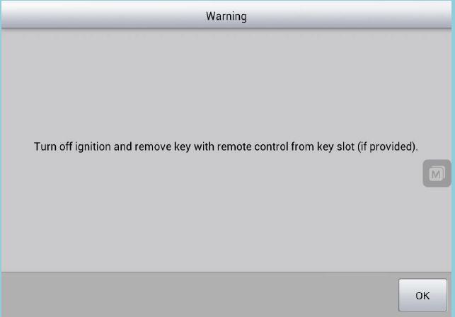
Turn off ignition and remove the key, and then tap ‘OK’ to start CAS programming.
After CAS programming is complete, switching on ignition is required, as shown in figure 23.
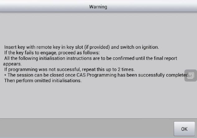
Switch on ignition, and tap ‘OK’ to complete CAS programming.
MaxiSys Pro will generate a final report after executing the plan. You can scroll through the list by sweeping your finger up and down to see more information.
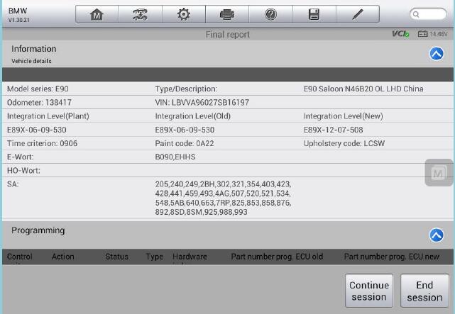
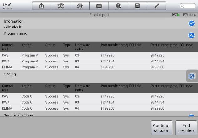
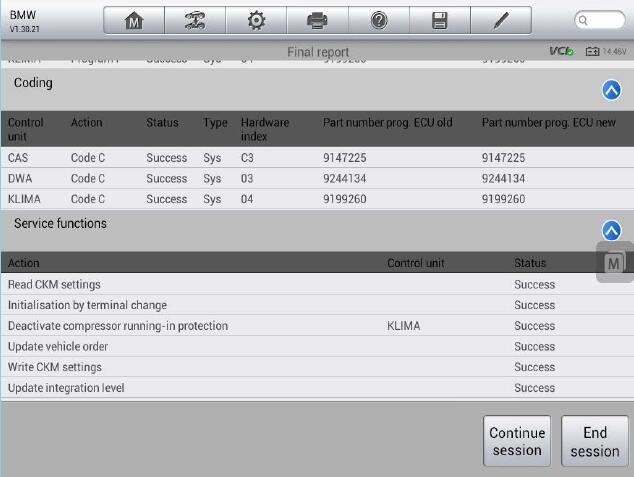
The information after executing the plan is available in this report, including the status of a single task, which can be viewed in the Status column.
Tap ‘End session’ to exit CIP, or tap ‘Continue session’ to continue programming. After tapping ‘Continue session’, MaxiSys Pro will read configuration information from vehicle again and communicate with each control unit. It will take several minutes, which is based upon vehicle specifications.
3.2 Complete Update
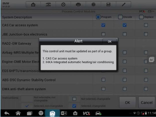
Complete Update shows a list of control units, as shown in figure 3.14
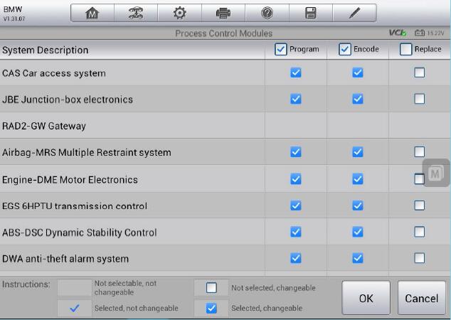
All the control units available to programming or coding are checked by default. You can manually select the corresponding items of each control unit to make any change. If the selected control unit must be programming or coding as part of a group, MaxiSys Pro will automatically select the related control units and display their names.
Some items may not be selectable, and the possible causes are as below,
– Programming or coding is not available for the control unit
– The control unit has error or needs to be replaced. Please refer to Initial Report in CIP Main Interface for detailed information.
Tap ‘OK’ after making your selection and MaxiSys Pro will determine a plan. Please refer to 3.1 Determine Measures Plan for additional information.
3.3 Selective Update
Please refer to 3.2 Complete Update for additional information about Selective Update. Programming and coding items only for control units needing to be updated are selected by default for Selective Update, which is the difference from Complete
Update.
3.4 Control Unit List
Control Unit List displays all the control units, as shown in figure 3.16. You can scroll through the list by sweeping your finger left and right to see more information.
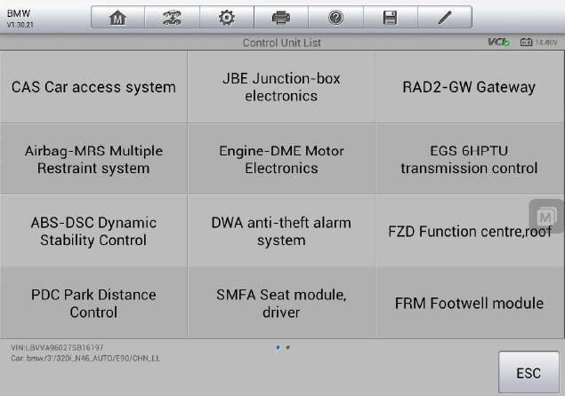
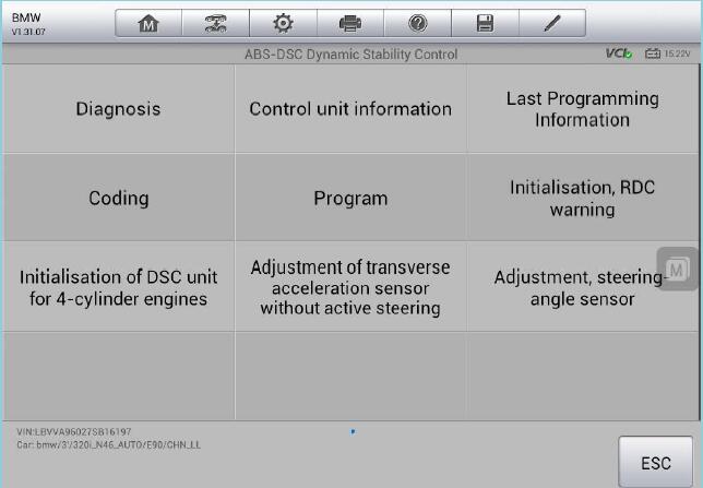
Tap the corresponding control unit to view the diagnostic information, control unit information, and the last programming information; to perform programming or coding; or to perform some related special functions.
https://www.obd2tool.com