
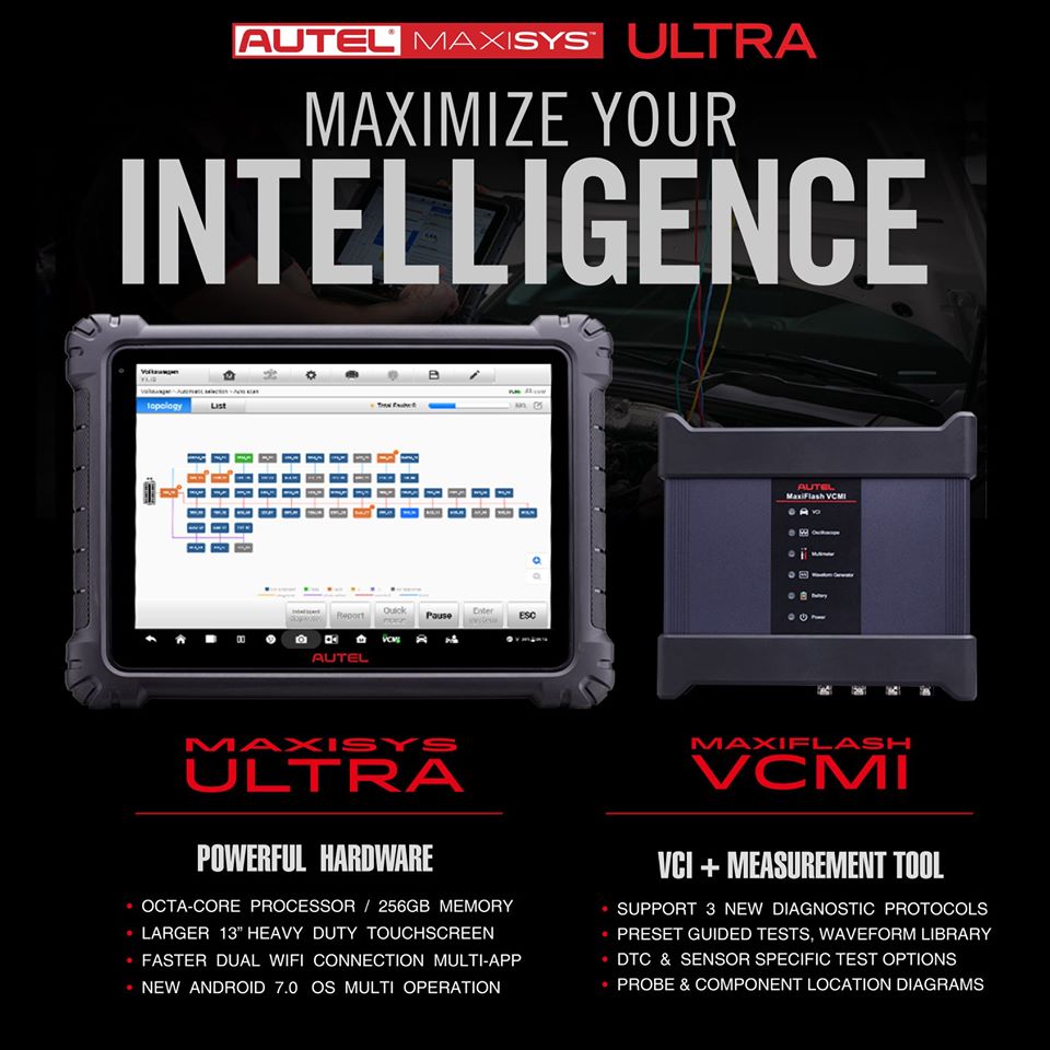
The MaxiSYS Ultra is Autel’s most ambitious diagnostics tablet designed to maximize technician intelligence. It features a 13-inch touchscreen tablet with Android 7.0 OS powered by an Octa-core processor (2.3GHz Quad + 1.7GHz Quad), substantial 256GB built-in memory, all powering the new split-screen multi-application navigation to provide diagnostic guidance and test components to confirm repairs. Combined with the dynamic topology module mapping, enhanced AutoSCAN features and Intelligent Diagnostics options, the Ultra offers the technicians step-by-step repair guidance. The new MaxiFlash VCMI functions as a 4-channel oscilloscope, waveform generator, multimeter, and CAN BUS tester. The convenient docking station featured ensures you always have the power to scan.
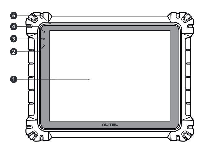
1.12.9″ TFT-LCD Capacitive Touch Screen
2.Ambient Light Sensor – detects ambient brightness
3.Power LED
4.Front Camera
5.Microphone
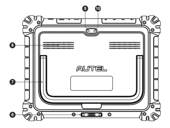
6.Docking Station Port
7.Collapsible Stand – extends from the back to allow hands-free viewing of the tablet
8.Speaker
9.Rear Camera
10.Camera Flash
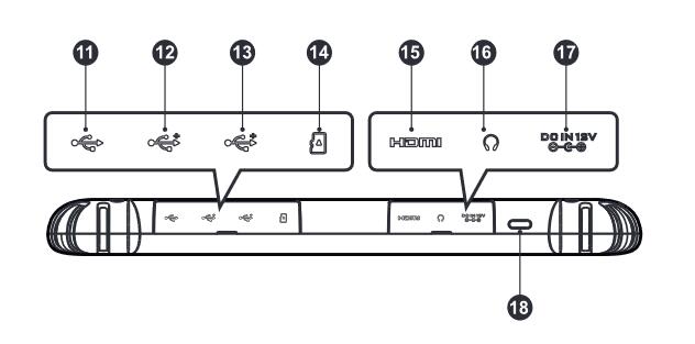
11.Mini USB Port – cannot be used with the USB port simultaneously
12.USB Port
13.USB Port
14.M 吓 SD Card Slot
15.HDMI (High-Definition Multimedia Interface) Port
16.Headphone Jack
17.DC Power Supply Input Port
18.Lock/Power Button – long press to turn on and off the Display Tablet, or tap power button to lock the screen
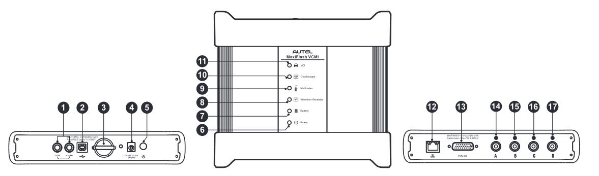
1.Multimeter Jacks
2.USB Port
3.Hook
4.DC Power Supply Input Port
5.Power Button
6.Power LED – refer to Table 1-1 Power LED Description for details
7.Battery LED – refer to Table 1-2 Battery LED Description for details
8.Waveform Generator LED – lights green when operating in the waveform generator mode
9.Multimeter LED – lights green when operating in the multimeter mode
10.
Oscilloscope LED – flashes green when operating in the oscilloscope mode
11.Vehicle LED – refer to Table 1-3 Vehicle LED Description for details
12.Ethernet Port
13.Vehicle Data Connector (DB26-Pin)
14.Input Channel A
15.Input Channel B
16.Input Channel C
17.Input Channel D